
How to Choose the Right 15kV 200A Loadbreak Junction?

Choosing the right 15kv 200a Loadbreak Junction begins with the field, not the catalog. The correct device must match system voltage, continuous current, fault-duty requirements, insulation level, and installation conditions. A compact junction may look suitable on paper. It can still fail when cable bending, moisture, or limited working space is ignored.

John D. McDonald, an IEEE Fellow and power-system engineering specialist, offers a practical reminder: “Good equipment selection starts with understanding the operating environment.” That principle matters here. A 15kv 200a Loadbreak Junction should fit the cable size, connector interface, grounding arrangement, and switching method used by the utility or industrial site. Check the manufacturer’s tested ratings. Do not rely only on nominal voltage and amperage.

Look closely at the enclosure.

Consider a roadside pad, a wet vault, or a crowded substation trench. Each location creates different stresses. Review loadbreak compatibility, deadbreak requirements, bushing dimensions, and installation torque. Confirm whether the junction supports future feeder expansion. That small detail can prevent expensive replacement work later.

Experience also teaches humility. Product data may appear complete, yet one missing detail can change the decision. Temperature, altitude, contamination, and maintenance access deserve careful review. Independent certification and traceable test documentation strengthen confidence. Supplier reputation helps, but it cannot replace engineering verification.

This guide explains how to compare construction, ratings, connector design, environmental protection, and project support. It also highlights common selection mistakes. Some are surprisingly easy to make. The best choice is not always the largest or most expensive unit. It is the junction that safely fits the real network, the real crew, and the real operating conditions.
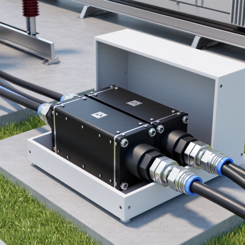
How to Choose the Right 15kV 200A Loadbreak Junction?

Understanding the Role of a 15kV 200A Loadbreak Junction

How to Choose the Right 15kV 200A Loadbreak Junction?

A 15kV 200A loadbreak junction provides a controlled connection point in medium-voltage distribution systems. It commonly interfaces with loadbreak elbows, cable terminations, and sectionalizing equipment. Its role is more than joining conductors. It helps crews isolate circuits, rearrange feeders, and maintain equipment with fewer unnecessary interruptions. However, it is not a complete switching device by itself. The connected components must support the intended loadbreak operation.

The voltage and current ratings are only the starting point. Confirm the insulation level, interface design, conductor range, and continuous current capability. Check the available fault rating as well. A junction rated for 200A may still be unsuitable for a system with higher short-circuit exposure.

Installation conditions also matter. Moisture, contamination, limited clearance, and repeated cable movement can affect long-term performance. Small details matter here.

In field planning, I would match the junction to the complete cable assembly, not select it from one catalog line. Verify elbow compatibility, shielding requirements, torque values, and grounding provisions. Follow the applicable utility procedures and manufacturer instructions. Qualified personnel should inspect the interface for contamination, damaged screens, or improper seating before energization. One common mistake is treating a generous rating as a safety guarantee. It is not. Some project assumptions may also need rechecking after fault studies or site surveys.

Checking Voltage, Current, and Loadbreak Compatibility

Selecting a 15kV 200A loadbreak junction starts with confirming the system voltage. A 15kV class rating does not mean the equipment suits every medium-voltage network. Check the highest operating voltage, insulation level, and required basic impulse insulation level. Review the cable insulation and shield design, too. A mismatch can create stress at the interface.

Then verify the current rating under real installation conditions. The 200A figure usually represents continuous current, not the maximum fault current. Check conductor size, ambient temperature, enclosure ventilation, and connector heating. Measure twice. A junction may carry 200A on paper but run hotter in a crowded cabinet. Inspect the contact surfaces and tighten connections to the specified torque. Loose hardware remains a common field problem.

Loadbreak compatibility requires closer attention. Confirm that the junction is designed for switching energized load current, not merely connecting a de-energized circuit. Review the rated loadbreak current, switching duty, operating frequency, and mating interface dimensions. The elbow, bushing, parking stand, and junction body must match as one system. Do not rely on appearance alone. Also check the manufacturer’s installation procedure and test requirements, including insulation resistance and phase identification. One practical weakness in many selections is incomplete documentation. If the rating table does not clearly separate loadbreak capacity from fault withstand capability, pause the purchase and request written clarification.

Selecting the Right Construction, Materials, and Bushing Design

How to Choose the Right 15kV 200A Loadbreak Junction?

Selecting the Right Construction, Materials, and Bushing Design

A 15kV 200A loadbreak junction must match the network, not just the catalog rating. Confirm the system voltage, continuous current, BIL, and short-circuit withstand requirements. Construction matters in wet vaults and compact switchgear. A sealed, dead-front body reduces exposure to moisture and accidental contact. Strong grounding provisions also support safer maintenance.

Material selection deserves close attention. Molded EPDM or silicone insulation can provide reliable weather resistance when properly manufactured and installed. Copper or aluminum conductor interfaces require compatible plating and torque control. Stainless steel hardware helps resist corrosion, especially near coastal or chemically active areas. Small details matter.

Tips: Check the bushing interface before ordering. It must match the elbow, parking stand, and operating tool. Verify dimensions on the actual cable, not an old drawing. Inspect sealing surfaces for cuts, dirt, or uneven compression. Never assume every 200A accessory fits every 15kV junction.

Bushing design affects installation effort and long-term confidence. Choose an interface with clear phase spacing, secure mechanical support, and accessible grounding points. A compact design may save space, but poor cable bending can stress the connection. Field inspections often find that the enclosure was selected correctly, while the cable geometry was overlooked. That is worth reconsidering.

How to Choose the Right 15kV 200A Loadbreak Junction?

Selecting the right construction, materials, and bushing design starts with confirming the electrical design envelope shown below.

The chart presents common reference values for a 15kV-class, 200A loadbreak junction: a 15.5kV maximum system voltage rating, 95kV basic impulse level, and 200A continuous/loadbreak current rating. Confirm the required BIL, fault-duty rating, environmental sealing, and interface compatibility against the applicable utility specification and project conditions.

Evaluating Installation Conditions, Safety, and Maintenance Needs

Choosing a 15kV 200A loadbreak junction starts with the installation environment, not the label. In field inspections, I check cabinet space, cable bending radius, and phase clearance before reviewing specifications. Confirm the system voltage, continuous current, fault-duty rating, and compatible cable interfaces. A 200A rating may not suit every operating condition. Temperature, altitude, and enclosure ventilation can change performance. Coastal sites need closer attention to salt deposits and corrosion. Underground vaults demand reliable sealing against water.

Safety depends on disciplined preparation.
Qualified personnel should isolate the circuit, apply lockout procedures, verify the absence of voltage, and install protective grounds. Use properly rated protective equipment and follow the applicable electrical code. During installation, clean interfaces carefully and use the specified torque. A loose connection can create heat inside an apparently quiet cabinet. That mistake is easy to overlook. Clear labeling also helps crews identify the correct circuit during urgent work.

Maintenance needs should influence the choice from day one. Look for accessible test points, replaceable sealing components, and enough working space for inspections. Record torque values, inspection dates, moisture findings, and unusual heating. Visual checks should include cracks, tracking marks, corrosion, and damaged cable jackets. Infrared scanning can reveal developing hot spots, but it cannot replace a de-energized inspection.

I have found that maintenance plans often assume perfect access. Real sites are less cooperative. Recheck the design after installation, especially when the junction sits near water, traffic, or repeated cable movement.

Comparing Standards, Supplier Quality, and Long-Term Value

How to Choose the Right 15kV 200A Loadbreak Junction?

Comparing Standards, Supplier Quality, and Long-Term Value

A 15kV 200A loadbreak junction must match the complete cable system, not only the voltage label. Check the applicable electrical standards, impulse withstand rating, continuous current rating, and loadbreak performance. Confirm the interface dimensions with your cable elbows and equipment bushings. A small mismatch can create overheating, partial discharge, or difficult installation.

Supplier quality deserves equal attention. Request type-test reports, routine inspection records, material specifications, and traceability for critical components. Reliable suppliers explain their testing methods clearly. They also provide installation instructions, torque values, and storage limits. In field inspections, poor cable preparation often causes failures, but connector design still matters. A certificate alone is not proof of consistent production. Audits, sample checks, and technical responses reveal more. Some suppliers may offer a lower price, yet replacement labor can quickly erase that saving.

Tips: Compare the total ownership cost. Include installation time, inspection needs, spare parts, outage risks, and expected service life. Ask whether sealing materials resist moisture, heat, and contamination at your site. Review actual project references, not polished claims alone. Keep one sample for dimensional verification before ordering in volume. This step feels slow. It can prevent an expensive mistake. Also, do not assume every 15kV product suits every network. System grounding, cable construction, and local conditions may change the selection.

How to Choose the Right 15kV 200A Loadbreak Junction? - Comparing Standards, Supplier Quality, and Long-Term Value

Evaluation Dimension Minimum Acceptable Benchmark Preferred Selection Criteria Evidence to Request Long-Term Value Impact
Voltage Class 15 kV class equipment suitable for the system operating voltage. Confirm compatibility with the utility's phase-to-phase and phase-to-ground operating conditions, including temporary overvoltage requirements. Product data sheet, system voltage schedule, and application approval record. Reduces insulation stress, premature failure, and costly retrofit work.
Continuous Current Rating At least 200 A continuous current at the stated ambient and installation conditions. Select a rating with practical thermal margin if the circuit operates near 200 A for extended periods. Continuous-current test report and derating data for enclosure, altitude, and ambient temperature. Lower connector temperature supports longer insulation and interface life.
Loadbreak Capability The complete junction and compatible mating components must be rated for 200 A loadbreak operation. Verify the exact operating sequence, tool requirements, switching frequency, and allowable load conditions. Type-test certificate, operating instructions, and approved mating-component list. Improves crew safety and avoids unplanned outages caused by incompatible interfaces.
Applicable Standards Design and testing aligned with IEEE Std 386 for separable insulated connector systems, where applicable. Require the current edition of the applicable standard and confirm that the tested configuration matches the supplied assembly. Standards compliance statement, test laboratory details, test dates, and configuration photographs. Creates a consistent technical basis for acceptance, inspection, and future replacement.
Interface Compatibility Correct electrical and mechanical interface for the cable, elbow, bushing, parking position, and grounding arrangement. Use a documented interface drawing with dimensions, conductor range, shield arrangement, and torque values. Certified dimensional drawing, cable compatibility matrix, and installation procedure. Minimizes installation errors, partial discharge risk, and field modification.
Short-Time Withstand Short-circuit withstand must meet the system fault-duty requirement for the specified duration. Evaluate the complete current path, including contacts, screens, grounding components, and mechanical restraint. Short-time current and peak withstand test results, with the tested duration clearly stated. Protects equipment during faults and reduces the probability of secondary damage.
Insulation and Sealing Insulating and semiconductive materials must be suitable for medium-voltage outdoor or indoor service as specified. Prefer molded stress-control components with documented moisture, ozone, UV, and thermal-aging performance. Material declarations, environmental test results, ingress protection information, and aging data. Slows water-treeing, tracking, corrosion, and environmental degradation.
Contact and Conductor Design Conductor and contact materials must support the required current, temperature, and fault-duty levels. Look for corrosion-resistant contact surfaces, controlled contact pressure, and verified conductor-size coverage. Material specifications, contact-resistance limits, crimp or compression data, and inspection records. Stable contact resistance reduces hot spots and maintenance frequency.
Supplier Quality System Documented quality controls for incoming materials, molding, assembly, and final inspection. Prefer a certified quality-management system, lot traceability, calibrated test equipment, and controlled process changes. Quality certificate, process flow, inspection plan, calibration records, and sample inspection report. Lowers batch-to-batch variation and improves replacement consistency.
Routine Production Testing Each production lot should receive documented electrical and visual checks appropriate to the design. Require routine withstand, dimensional, sealing, and contact-resistance checks where applicable. Lot test certificate, serial or batch number, acceptance limits, and nonconformance procedure. Provides early defect detection before equipment reaches the field.
Installation Risk Clear instructions covering cleaning, preparation, torque, grounding, phase spacing, and inspection. Prefer keyed or mistake-resistant features, visible installation indicators, and field training support. Illustrated installation manual, checklist, training record, and technical support response procedure. Reduces commissioning defects and rework labor.
Environmental Suitability Operating temperature, altitude, humidity, pollution level, and UV exposure must match the installation site. Select documented performance for the actual climate and enclosure conditions rather than relying only on nominal voltage. Environmental ratings, temperature range, altitude correction data, and outdoor exposure test information. Improves service life in coastal, industrial, high-altitude, and high-humidity locations.
Maintenance and Inspection Defined inspection points for visible damage, contamination, grounding, torque, and interface condition. Prefer condition-based inspection guidance and replaceable accessories where technically appropriate. Maintenance schedule, inspection checklist, replacement criteria, and recommended storage life. Makes preventive maintenance predictable and reduces emergency replacement costs.
Warranty and Technical Support Written warranty terms covering material and manufacturing defects, with defined claim requirements. Evaluate response time, spare-parts availability, application engineering, and failure-analysis support. Warranty document, service-level commitment, escalation process, and technical contact details. Shortens outage duration and improves lifecycle cost control.
Total Cost of Ownership Purchase price must be assessed together with installation, testing, maintenance, spares, and outage costs. Choose the option with the strongest documented reliability and compatibility, not simply the lowest initial price. Five- to fifteen-year cost model, failure history, lead time, spare strategy, and disposal requirements. Balances capital expenditure against outage risk, labor, replacements, and service continuity.
Selection note: A 15 kV, 200 A designation alone does not confirm suitability. The complete loadbreak junction assembly, mating interfaces, cable dimensions, grounding method, short-circuit duty, environmental conditions, and applicable utility requirements should be verified together before approval.
Reference framework: IEEE Std 386 is commonly used for separable insulated connector systems. Additional requirements may apply under local electrical codes, utility specifications, installation standards, and the current edition of the applicable product standard.

Product Added

Go to Quote Request Form

Continue Product Search