What Are the Top Types of Step Up Transformers?
A Step Up Transformer increases AC voltage from its primary winding to its secondary winding. The voltage change depends mainly on the turns ratio, while the available output also depends on the unit’s rating and operating conditions. These transformers support applications ranging from laboratory equipment and industrial systems to power transmission. Their requirements differ.
The main designs include two-winding transformers and autotransformers. A two-winding model uses separate primary and secondary windings, providing electrical isolation between input and output. An autotransformer shares part of its winding, which can make it smaller and more economical for certain voltage changes. But it does not provide the same isolation. That distinction matters. Core construction, phase configuration, and cooling method also shape a transformer’s suitability. For example, single-phase and three-phase units serve different supply systems, while dry-type and oil-immersed designs manage heat in different ways.
This guide compares the top types of Step Up Transformer by design, benefits, limitations, and common uses. It also explains practical selection factors, including input and output voltage, load capacity, frequency, installation environment, and safety requirements. A nameplate is a useful starting point, not the whole story. Real operating conditions can expose details that a quick comparison misses. There is no universal winner; the right choice depends on the system and its constraints. Some categories overlap, so comparing labels alone can be misleading.
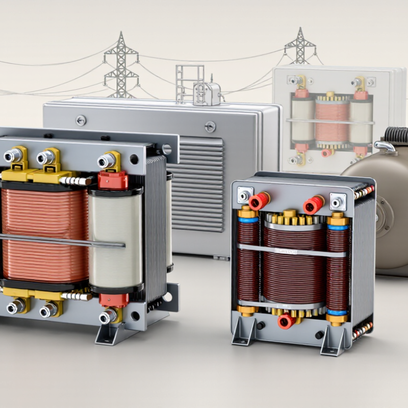
How Step-Up Transformers Increase Voltage
A step-up transformer raises AC voltage through electromagnetic induction. Its primary winding receives alternating current, which creates a changing magnetic field in the core. That field induces voltage in the secondary winding. When the secondary has more turns than the primary, its voltage is higher. The turns ratio sets the ideal relationship: doubling the secondary turns approximately doubles the voltage.
The change has a trade-off. Not more energy. In an ideal transformer, higher output voltage means lower output current for similar power. Real units also lose some energy as heat in the windings and core. A transformer’s actual output depends on its design, supply frequency, and connected load. For example, a unit rated for a particular voltage may deliver less under heavy load. It can also overheat if pushed beyond its rating.
This detail is easy to miss: a transformer does not raise steady DC voltage by itself, because it needs a changing magnetic field. Even with AC, the voltage ratio alone does not confirm safe operation. Insulation, cooling, and rated capacity matter. Check the equipment specifications, and leave live electrical testing to qualified professionals. A little caution goes a long way.
Single-Phase Step-Up Transformers
Single-Phase Step-Up Transformers
A single-phase step-up transformer raises alternating-current voltage through a higher-turn secondary winding. It suits small buildings, rural feeders, and equipment needing a higher supply voltage. For a fixed power demand, higher voltage can mean lower current, but real losses remain. Core material, winding resistance, load, and cooling all matter. A transformer can feel warm under sustained load; warmth alone does not confirm a fault. The U.S. Department of Energy’s distribution-transformer technical analysis estimated roughly 61 billion kilowatt-hours of annual losses across U.S. distribution transformers. That broad estimate does not isolate single-phase units, so it is useful context, not a product-level prediction.
Tips: Check input and output voltage, frequency, kVA rating, and load-starting current before selection. Leave room for ventilation, and follow the manufacturer’s installation instructions. A common oversight is choosing by voltage alone. The DOE’s distribution-transformer efficiency standards also make efficiency a practical comparison point; review the applicable rating data rather than assuming that a higher output voltage means better performance. Shorter cable runs can help limit voltage drop. Measure under the actual load when possible.
Three-Phase Step-Up Transformers
Three-phase step-up transformers raise generator voltage for transmission or industrial distribution. A unit may use one three-phase core or a bank of three single-phase transformers. Both arrangements have trade-offs. A single unit can save space, while a bank may be easier to transport or maintain. For the same transmitted power, higher voltage usually means lower current and reduced line losses. The actual benefit depends on the cables, load, and operating conditions. That detail is easy to overlook.
Choosing a transformer involves more than matching input and output voltage. Engineers also check rated power, frequency, insulation level, cooling method, and the system’s grounding needs. The vector group matters because it affects phase relationships and how the transformer connects with nearby equipment. Small details matter. At a plant, technicians may verify winding resistance, insulation condition, protection settings, and temperature sensors before energizing the unit. A tap changer can help manage voltage variation, but its operating range and switching method must fit the application. A calculation may look neat on paper; real loads can fluctuate, and assumptions deserve review.
Two-Winding Step-Up Transformers and Autotransformers
Two-winding step-up transformers use separate primary and secondary coils to raise voltage. The electrical separation also provides galvanic isolation between input and output. That can be valuable where equipment needs an isolated supply or where system design calls for a clear separation. For example, a transformer may raise a generator’s output voltage before power travels through a distribution line. That matters.
An autotransformer uses one continuous winding, with a shared section serving both input and output circuits. This design can make the unit smaller, lighter, and more efficient when the voltage increase is modest. It may suit installations where space is limited and electrical isolation is not required. No isolation. The simpler construction can look like an easy choice, but that comparison can mislead: shared windings change the protection and grounding considerations.
Selection depends on more than the voltage ratio. Check the load’s power demand, expected operating conditions, insulation requirements, and available fault protection. A motor, for instance, may draw much higher current during startup than during steady operation. An autotransformer that appears adequate on a rating sheet may need a closer review of that surge. The right choice depends on the whole installation, not just the input and output voltages.
Special-Purpose Step-Up Transformers for Power and Electronics
Special-Purpose Step-Up Transformers for Power and Electronics
Special-purpose step-up transformers are built around the load, not just a voltage ratio. Rectifier units supply higher-voltage DC systems, while inverter-coupled units raise converter output for grid connection. Traction and test systems may need different insulation, cooling, and short-circuit performance. Harmonics matter. A transformer selected only by kilovolt-amperes can overheat when electronic loads distort current. Engineers therefore check the waveform, duty cycle, impedance, and cooling conditions before choosing a design. Small details change the result.
Renewable power growth makes these choices increasingly relevant. IRENA’s Renewable Capacity Statistics 2024 reports that global renewable capacity reached about 3,870 GW in 2023, after 473 GW of additions that year. The IEA’s Electricity Grids and Secure Energy Transitions says annual grid investment needs to rise to more than USD 600 billion by 2030. Those figures signal expanding grid equipment needs, though they do not predict transformer demand on their own. In practice, a unit serving an inverter may need to handle frequent output changes and harmonic heating. I would not assume one standard design fits every site; ambient heat and enclosure ventilation can still upset a seemingly sound specification. Check the load data against the actual operating conditions.
