What Is a Pick and Place Machine?
A pick and place machine is automated equipment that lifts electronic components and positions them on a printed circuit board. In electronics manufacturing, it commonly places surface-mount devices after solder paste has been applied. A feeder presents each part, a vision system checks its orientation, and a placement head moves it to a programmed location. Small resistors may be placed at high speed, while fine-pitch chips demand careful alignment. It looks straightforward. It is not always.
A Place Machine can be part of a compact production line or a high-volume assembly system. Its results depend on more than placement speed: nozzle choice, feeder setup, board support, calibration, and component data all matter. Most systems use cameras and programmed coordinates to correct small positional differences, though not every error can be fixed automatically. Operators still need to verify setup and review inspection results. That detail is easy to overlook.
This guide explains how pick and place machines work, which types are available, and what to assess before choosing one. It also considers accuracy, throughput, operating costs, and maintenance. Specifications tell only part of the story; actual performance depends on board design and process consistency. A careful comparison helps manufacturers match equipment to production needs without paying for capacity they cannot use.
What Is a Pick-and-Place Machine in Automated Assembly?
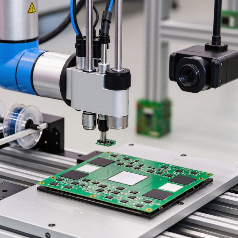
A pick-and-place machine moves parts from a supply point to precise positions during automated assembly. A feeder presents each component, while a nozzle or gripper lifts it and places it into a fixture, onto a circuit board, or into another assembly. Cameras may check part orientation and placement before the next step begins.
In a production line, the machine follows programmed coordinates and timing. Conveyors, sensors, and assembly software help coordinate its movements with nearby equipment. Some systems handle tiny electronic components; others place larger parts with mechanical grippers. The right setup depends on part size, shape, weight, and required placement accuracy. Small parts matter. A slightly tilted component can cause a later operation to fail.
Reliable results require more than fast movement. Operators need to load parts consistently, maintain clean nozzles or grippers, and verify camera settings. The first setup is rarely perfect. Reflective surfaces, flexible parts, or crowded trays can confuse vision systems, so testing with actual components is essential. A slower cycle may be the better choice when it reduces misplacement and rework. That takes tuning. Even with good automation, people still need to inspect exceptions and adjust the process when parts or materials change.
What Is a Pick-and-Place Machine in Automated Assembly?
A pick-and-place machine positions electronic components on a printed circuit board (PCB), commonly after solder paste has been applied and before the board enters a reflow oven.
| Machine Type | How It Places Components | Typical Nominal Placement Rate | Common Fit | Main Considerations |
| Benchtop or entry-level | A compact placement head picks parts from tape, trays, or other feeders and places them using programmed coordinates, often with operator assistance. | About 1,000–10,000 components per hour | Prototypes, small batches, and lower-volume PCB assembly | Lower throughput; setup and operator input can strongly affect production time. |
| Flexible production machine | Vision systems help align components with PCB pads; multiple nozzles and feeder positions support a broad mix of parts. | About 10,000–40,000 components per hour | Mixed-product lines and medium-volume assembly | A wider component range may reduce speed; changeovers and feeder setup need planning. |
| High-speed production machine | Optimized heads and feeder layouts place large numbers of small, commonly used components at high speed. | About 40,000–100,000+ components per hour | High-volume production with repeatable board designs | Best rates depend on component mix, board layout, feeder arrangement, and line balance. |
Key Factors That Affect Placement
| Factor | Why It Matters |
| Component type and size | Small chip components, fine-pitch ICs, and larger or irregular parts can require different nozzles, handling methods, and placement speeds. |
| Vision and alignment | Optical inspection can correct component position and orientation before placement, helping align leads or contacts with PCB pads. |
| Feeders and changeovers | Feeder capacity, component loading, and the time needed to switch between board designs affect overall line productivity. |
| Board and line conditions | PCB size, component spacing, placement program, inspection requirements, and upstream or downstream equipment all influence actual output. |
Placement-rate figures are broad illustrative ranges, not guaranteed production output. Actual performance varies by machine configuration, board design, component mix, and operating conditions.
How Does It Detect, Pick Up, and Position Components?
A pick-and-place machine uses cameras, lighting, and programmed coordinates to locate each component before placement. A board camera reads fiducial marks, fixing the circuit board’s position and rotation. A second camera can inspect a component held by the nozzle. It checks the component’s shape, orientation, and center, then calculates small corrections.
That sounds simple. It is not always. Reflective metal leads, tiny parts, or uneven lighting can confuse vision systems. The machine may reject a part rather than place it incorrectly. A vacuum nozzle lifts accepted components from a tape feeder, while pressure sensors can help detect whether a part was picked up. The head then moves over the board, adjusts its angle, and lowers the component onto solder paste. Calibration matters: a slightly misaligned camera or worn nozzle can shift placements across many boards.
The International Federation of Robotics’ World Robotics 2024 report recorded 541,302 industrial robot installations worldwide in 2023, including 125,804 in the electrical and electronics industry. These figures cover industrial robots broadly, not pick-and-place machines alone, but they show automation’s substantial role in electronics production. In practice, operators still need to check feeder setup, nozzle condition, and inspection results. Vision helps, but it does not remove every source of error.
Which Feeders, Nozzles, Cameras, and Motion Systems Enable Placement?
What Is a Pick and Place Machine?
A pick-and-place machine moves electronic components from feeders onto a printed circuit board. Feeders present parts at consistent pickup points, but consistency depends on correct loading and setup. Tape feeders suit many small components; trays and tubes handle parts with different shapes or packaging. A misplaced strip can cause repeated pickup errors. Small details matter.
A nozzle creates the contact needed to lift each component. Its size and shape should match the part, since a poor fit can tilt or drop it. Cameras check component orientation and board fiducials before placement. Motion systems then coordinate the head, board, and placement position. Their accuracy depends on calibration, stiffness, and speed settings. Faster is not always better. A setup may look sound on paper, yet still need adjustment during production.
Tips: Check feeder alignment, nozzle wear, and camera focus during routine changeovers. Run a small test batch after setup, then inspect placement accuracy and component orientation. Keep notes on recurring faults; one missed detail can distort the next setup.
What Is a Pick and Place Machine? Which Feeders, Nozzles, Cameras, and Motion Systems Enable Placement?
A pick-and-place machine positions electronic components on a circuit board. Feeders present components in sequence, vacuum nozzles pick them up, cameras help verify and align them, and the motion system moves the head or board to the placement location.
Tape Pitch and Theoretical Feeder Capacity
These values are calculated as 1,000 mm divided by the pocket pitch, assuming one component per pocket. They represent theoretical capacity; tape leaders, trailers, and empty pockets reduce the usable count.
How Do SMT Platforms Compare at 20,000–100,000+ Components per Hour?
A pick-and-place machine’s headline speed can be misleading. At 20,000 components per hour, it averages about 5.6 placements per second; at 100,000, about 27.8. These are nominal rates, not guaranteed board output. Feeder changes, component spacing, nozzle changes, and inspection stops all reduce real throughput. IPC-9850, an industry standard for characterizing placement equipment, offers a more disciplined comparison than catalog speed alone.
Around 20,000 CPH, a platform may suit varied boards, larger components, or frequent product changes. Near 100,000 CPH and above, machines typically rely on tightly organized feeders, optimized board flow, and high-speed placement heads. The trade-off is real: a fast machine can wait while a slower process prints solder paste or cures a board. Compare verified placements on your own board, including accuracy, changeover time, and downtime—not just the best-case rating. Small details matter. A misplaced feeder can erase the promised gain.
Tips: Ask suppliers for sustained throughput on a representative board, not an idealized test pattern. Record good boards per hour across a full shift. IPC-9850 helps frame equipment comparisons, but it cannot predict every factory’s mix. That leaves some judgment—and occasional surprises.
Where Are Pick-and-Place Machines Used in Electronics Manufacturing?
A pick-and-place machine mounts electronic components onto printed circuit boards (PCBs). In a typical surface-mount technology line, it follows solder-paste printing and component placement, then the board passes through a reflow oven. Small resistors may sit beside fine-pitch chips. Vision cameras check alignment before placement.
These machines are used across consumer-electronics, automotive, telecommunications, medical-device, and industrial-control production. They handle high-volume boards for phones and routers, as well as control modules with mixed component sizes. Speed is useful, but changeovers matter: feeders, nozzles, and programming must match each board. A prototype line may favor flexible setup over maximum placement speed. Small detail, big impact.
Demand for electronic components provides useful context. The Semiconductor Industry Association reported global semiconductor sales of $627.6 billion in 2024, up 19.1% from 2023. This figure measures chip sales, not pick-and-place installations, but it reflects the scale of electronics demand these production lines serve.
In practice, placement is only one quality checkpoint. Poor solder-paste printing or a warped PCB can still cause defects. Fast machines cannot fix every upstream problem.
